
 日本語
 中文
 Deutsch
 Español

Solder Spikes in Robotic Soldering: Not Only a Flux Problem [Steve Column]
Table of Contents
- What Is a Solder Spike? — Solder Drawn Out as the Tip Lifts Off
- Flux’s Two Roles
- When Flux Deactivates First
- When Heat Doesn’t Get Through
- Opposite Countermeasures
- Seeing Where and When It Formed
- Summary
- Related Products & Services
- Video for This Tech Article

Video for this Tech Article
What Is a Solder Spike? — Solder Drawn Out as the Tip Lifts Off
S Hello everyone. I’m Steve, a soldering engineer at Japan Unix.
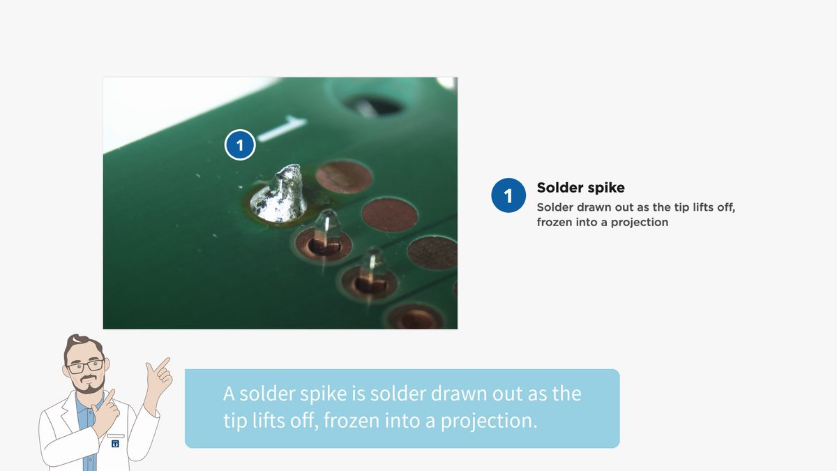
Today, I’ll talk about solder spikes, also known as icicles, a defect in iron-tip automated soldering.

A solder spike is solder drawn out as the tip lifts off, frozen into a projection. Now, let’s look at how spikes form.
Flux’s Two Roles
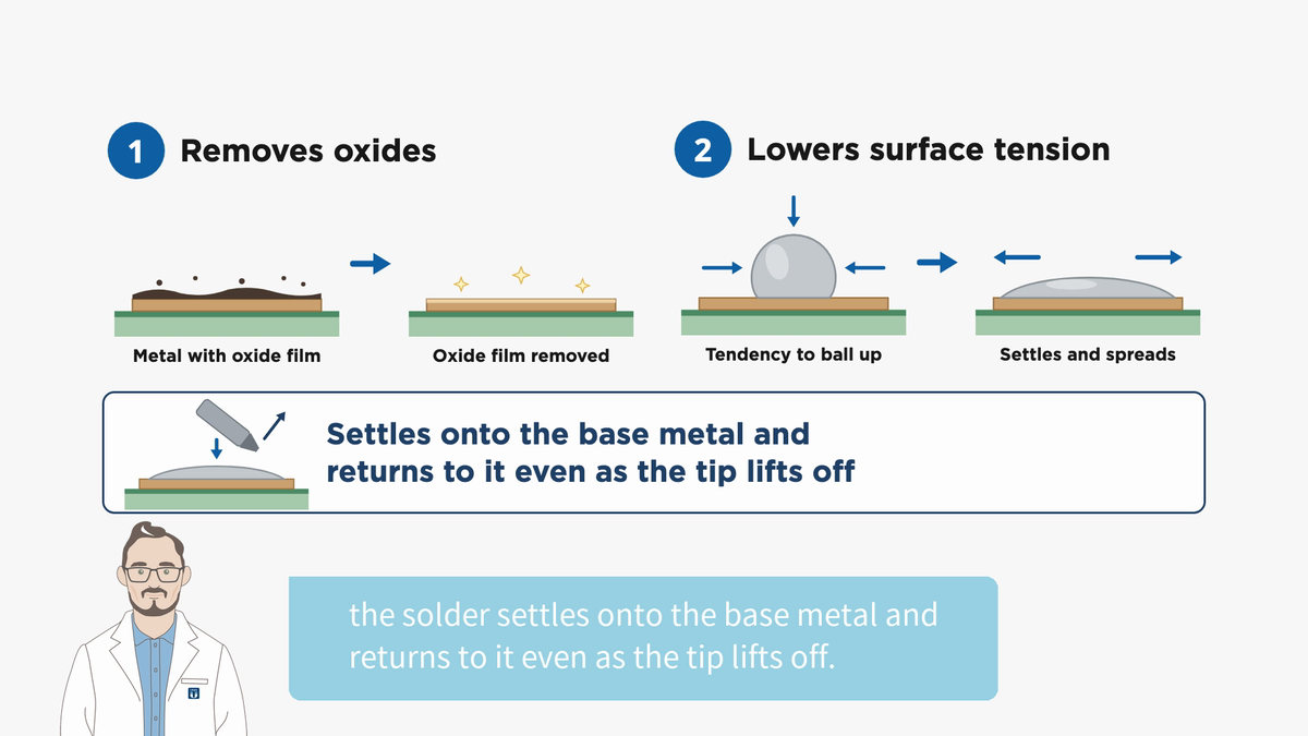
S Flux plays two roles: it removes oxides and lowers the solder’s surface tension. With the oxides gone and the tendency to ball up weakened, the solder settles onto the base metal and returns to it even as the tip lifts off.
When Flux Deactivates First
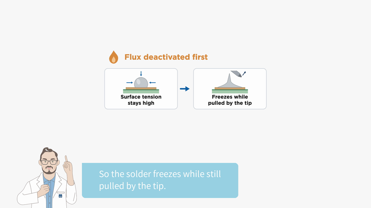
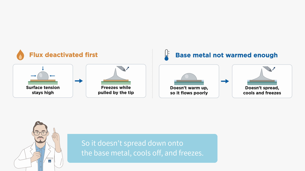
S But when the flux is deactivated first, it no longer lowers the surface tension. So the solder freezes while still pulled by the tip.
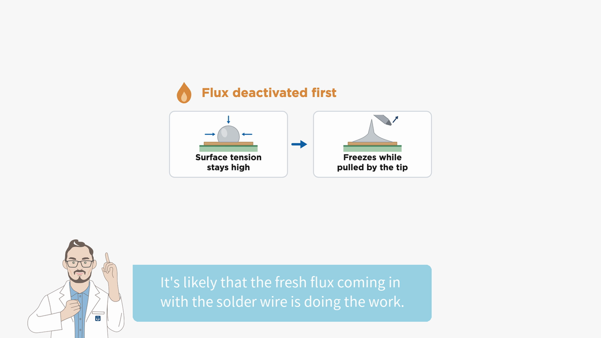
Adding solder can make a spike go away, but not necessarily because there’s more solder. It’s likely that the fresh flux coming in with the solder wire is doing the work.
When Heat Doesn’t Get Through
S On the other hand, too little heat produces a very similar spike. Without the base metal warming up, the solder doesn’t flow easily. So it doesn’t spread down onto the base metal, cools off, and freezes.
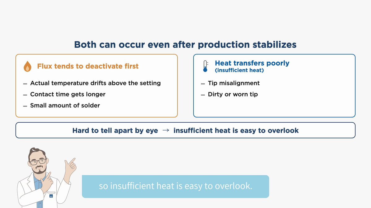
Both kinds of spike can occur after production has stabilized. The actual temperature drifting above the setting, the contact time getting longer, or a small amount of solder. These are changes that make the flux more likely to deactivate first. When the tip is misaligned, dirty, or worn, heat transfers less easily, so insufficient heat becomes more likely. The two are hard to tell apart by eye, and flux is suspected first, so insufficient heat is easy to overlook.
Opposite Countermeasures
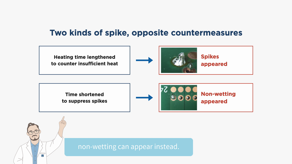
S What’s more, the countermeasures for the two kinds of spike are exact opposites. When the heating time is lengthened to counter insufficient heat, the flux can deactivate, leading to spikes. Conversely, when the time is shortened to suppress spikes, non-wetting can appear instead.
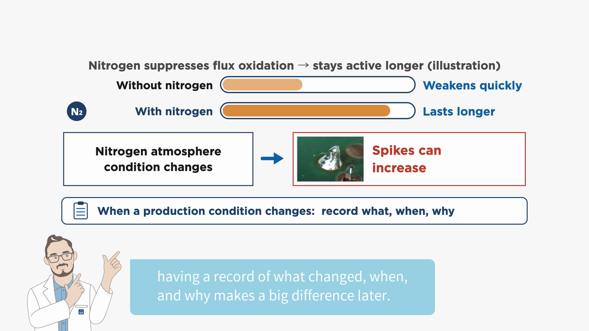
In a nitrogen atmosphere, oxidation of the flux is suppressed, so the flux stays active longer. When that condition changes, spikes can increase. When a condition is changed in production, having a record of what changed, when, and why makes a big difference later.
Seeing Where and When It Formed
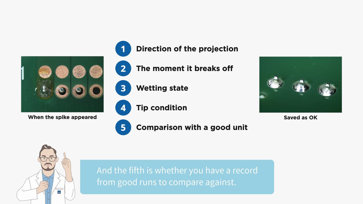
S Seeing where and when a spike forms, in real time, gives you more information than the look of the frozen shape. The points to watch: the direction of the projection, the moment it breaks off, the wetting state, and the tip condition. And the fifth is whether you have a record from good runs to compare against.
Neither what I have said so far nor the points below is a procedure for changing anything. Any actual change to a setting, condition, or material is a decision for you to make, under your own change-management procedure (4M change control) and with your own approval.
- Direction of the projection
- The moment it breaks off
- Wetting state
- Tip condition
- Comparison with a good unit — a record from good runs to compare against
Summary
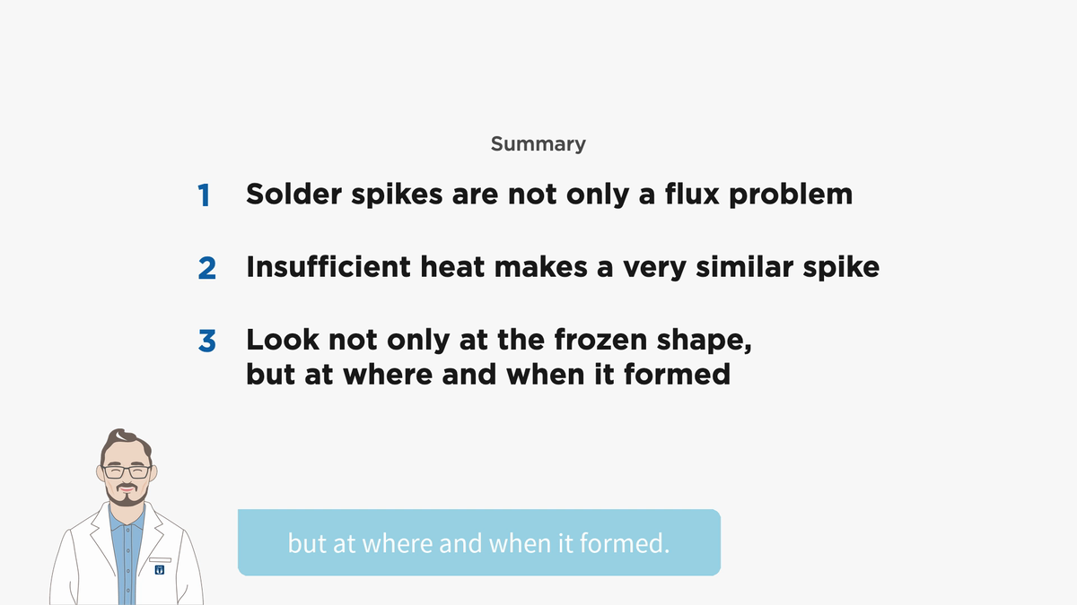
- Solder spikes are not only a flux problem
- Insufficient heat makes a very similar spike
- Look not only at the frozen shape, but at where and when it formed
S Solder spikes are not only a flux problem. Insufficient heat can cause them too. Today was about looking not only at the frozen shape, but at where and when it formed.

When solder spikes appear: what to check before you change anything, in one checklist.
The full checklist is in this one PDF. Soldering Defect Troubleshooting Checklist (2 pages) — page 1 is the scan-and-check page for the floor, page 2 explains why each point is checked.
Download the Soldering Defect Troubleshooting Checklist (Free)
If you have other questions, feel free to reach out to Japan Unix.
Related Products & Services
Video for This Tech Article
Related document: Soldering Defect Troubleshooting Checklist (Free)