
 日本語
日本語 中文
中文 Deutsch
 Español
Iron Tip Selection Criteria and Basic Knowledge
Iron Tip Selection Criteria and Basic Knowledge
Three Requirement
How to select the tip shape and dimensions best appropriated for the soldering point of the target device (component or workpiece)
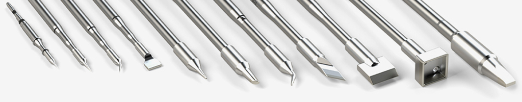
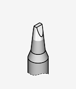
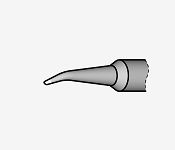
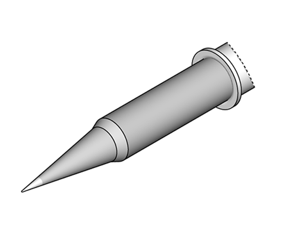
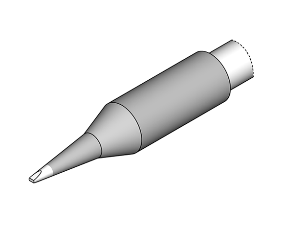
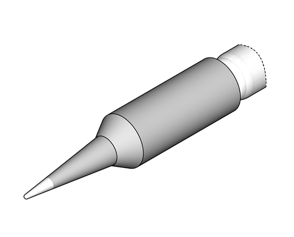
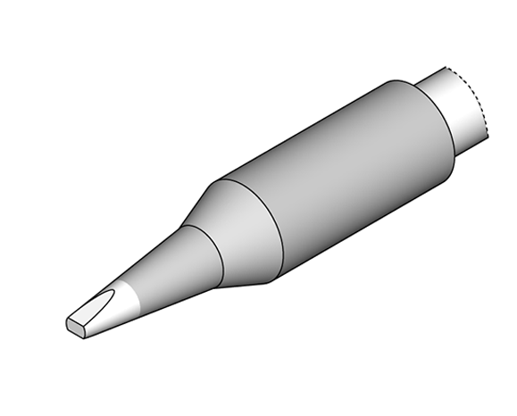
1)Basic Shape
The shape of the soldering point, the shape of the land on the board and the electrode of the component, and the shape of the tip that makes maximum contact with the contact point are selected.
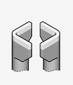
2)Angle of Approach
If a straight approach cannot provide optimum contact due to component placement or component shape on the board, a bented tip angle is required.
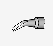
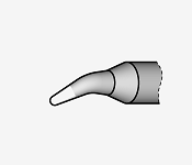
Example of bented iron tips
Example of using bented type
Even in soldering positions where it is possible to use a normal straight type soldering iron, the use of a bented type tip makes soldering work easier and more accurate in areas where it is difficult to feel the wrist and maintain a stable posture. This is especially advantageous for I- and J-lead components.
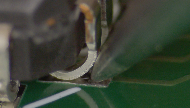
Originally, if the tip is laid down more, the contact surface will be wider.
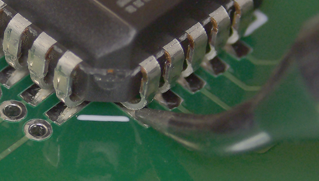
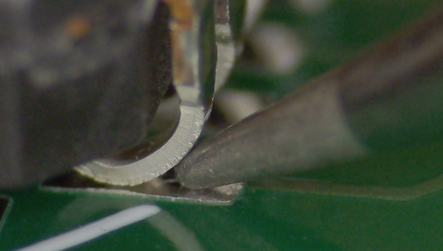
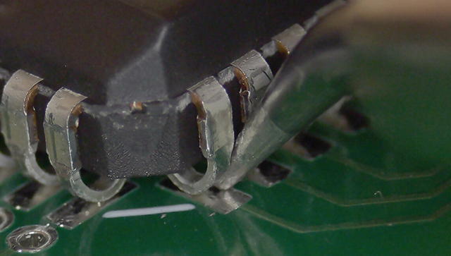
The use of the bented type iron shows that the tip goes deeper and the contact surface is wider, even in the same posture. The rightmost picture shows that the bented type can be used in an upright position when wetting is required on the side or back surface of a pin.
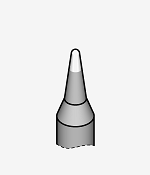
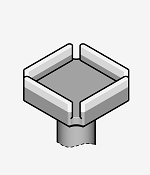
3)Heat Capacity
Even if the iron tip can approach, it may not maintain a appropriate temperature depending on the required heat capacity of the component, board pattern, thermal plane, etc. In this case, select a tip shape that has a higher heat capacity.
Normal heat capacity
Higher heat capacity
In the first place, why does solder wet on metal materials?
A molten solder alloy is poured into the gap between metal and metal (generally copper) with clean surfaces. Solder wetting, diffusion of copper and tin atoms, and intermetallic compounds are formed. This is soldering to electronic devices.The most important role of the soldering tip is to transfer heat properly to the soldered area. Therefore, the correct soldering tip is necessary for proper heat transfer.In addition to temperature and tip, the metal composition of the solder and the performance of the flux are also necessary for soldering.
What are the important requirements for heat transfer?
Figure 3) Temperature Difference at Iron Tip
Figure4) Contact Area: Tip width and Pad width
Figure5) Contact Area: Heat Bridge
1) Temperature difference
Pay attention to the temperature difference of the iron tip!The higher the temperature of the soldering iron tip, the more and faster heat is transferred to the target area. However, each device has its own heat resistance characteristics and limits, and a high-temperature iron tip can cause various workability problems. For this reason, 350degrees[Celsius] for lead-free solder and 330degrees[Celsius] for lead-containing (eutectic) solder are considered appropriate temperatures.
To perform soldering without difficulty, it is recommended to set the tip temperature at the melting point of the solder material + 100 to 150degrees[Celsius]. Apply the soldering tip, add preliminary solder (heat bridge, Fig. 3-2), and perform the main soldering. If the tip temperature is set too high, the pattern will be damaged or the flux activity will be poor, making it unsuitable for soldering. If soldering cannot be performed at the proper temperature, it is either due to insufficient thermal capacity of the tip, thermal recovery, or heater capacity.
Temperature difference: tip temperature (Figure 3)(Figure 3-1) Soldering cannot be done if the tip temperature is low. If the temperature difference is small, heat transfer is slow and the solder does not reach the required temperature over time. (Figure 3-2) Generally, the optimum solder tip temperature is about 350degrees[Celsius] because heat is transferred most efficiently.
2) Contact Area
The contact area between the tip and the component is important!The contact area between the tip and the electrode surface of the part, which is the source of heat transfer, changes the amount of heat transferred. Therefore, there is an optimal contact area for each part shape and type.
Contact Area: Tip Width (Figure 4)(Figure 4-1) Suitable tip width for the pad width ensures efficient heat transfer and sufficient contact area.
- According to IPC J-STD-001, it is recommended that the tip width and land width be about the same.
(Figure 4-2) Too wide a tip results in inefficient heat transfer, damage to the area around the soldering point, and a large possibility of excess solder debris (FOD) remaining on the surface.
Contact Area: Heat Bridge (Figure 5)(Figure 5-1) At the moment the tip contact with the soldering point, heat is not sufficiently transferred due to point contact (Figure 5-2) When a little solder is added (pre-soldering), the contact area increases due to melted solder, and heat is rapidly transferred to the solder contact point due to heat bridge (Figure 5-3) When sufficient heat has been transferred, feed main solder (Figure 5-4) (Figure 5-4) and remove the tip and allow it to cool.